

In the first part of this blog series I provided an overview of the FlashArray//m which was recently launched by Pure Storage.
In this next post I’m going to go a bit deeper into the following components that make up the solution:
- Overall Architecture
- NV-RAM
- PCIe non-transparent Bridge
- Flash Modules.
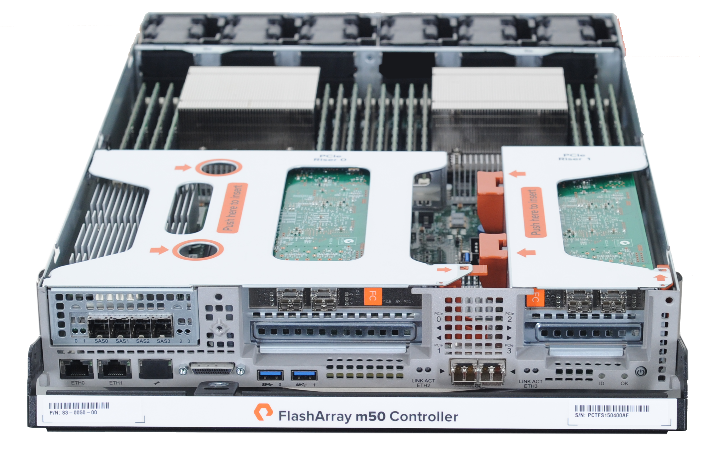
Overall Architecture
Firstly I wanted to cover some architectural design decisions of FlashArray //m, let’s start with the question – why manufacture your own hardware?
While this seems to be the case on first inspection, if you delve deeper into the solution you will see that really we are still leveraging commodity components with Intel CPU’s, DRAM Memory and Flash NAND SSDs, the only difference is in the way we’ve packaged these into a smaller, higher density platform providing the ability to leverage Moore’s Law for NAND Flash the same way CPU manufacturers have for decades leveraged the increase in transistor densities through R&D in manufacturing and fabrication techniques.
With the FlashArray//m , new technologies have been integrated into the platform now, so that they can be leveraged in the near future, think PCIe and NVMe.
NV-RAM
As part of the FlashArray//m architecture Pure Storage have developed our own NV-RAM technology, this has changed from utilising SLC SSD’s in the FA-400 series to a custom made NV-RAM module.
Taking into consideration the write limitations with NAND Flash technology (specifically the program/erase cycle) we’ve designed a storage system that coalesces writes in NV-RAM before spreading the data evenly across all the SSD’s in a FlashArray in a way that globally prolongs the life of the medium via FlashCare.
The new NV-RAM modules utilise a combination of DDR3 DRAM and NAND flash backed by Super Capacitors. The stored-up energy in the Super Capacitors is used to power the NV-RAM module during loss of power allowing for the de-staging of DRAM to NAND.

FlashArray//m utilises up to 4 of these hot swappable modules which are dual homed to both controllers and connect via PCIe utlising NVMe.
PCIe Non-Transparent Bridge
A PCIe non-transparent bridge (NTB) is a point-to-point PCIe bus that interconnects two systems while providing electrical isolation between them. This bridge can be used to provide HA connectivity between the two controllers, and also allows direct memory access between controller CPUs.
Previous models of FlashArray utilise an infiniband connection providing high speed connectivity between controllers for High Availability. With the FlashArray//m a non-transparent bridge has been introduced to reduce the number of components required to provide High Availability, which means less cabling complexity and increased native performance between controllers.
Note: There are sufficient PCIe slots in each controller to install an infiniband adaptor into a FlashArray//m for the purpose of non-disruptively migrating from previous controller models (I’ll cover this as part of a future blogpost).
Flash Modules
The Flash Module design introduces a new interposer that not only converts SATA to SAS but also provides interfaces for two SSD’s in each module. This doubling of density doesn’t just mean an increase in capacity, it also means there are now twice the number of SSD Controllers which also provides an increase in performance.
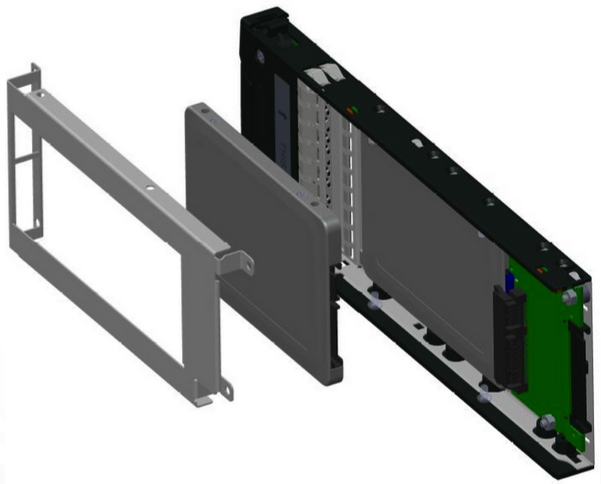
Each Flash Module is hot pluggable and dual homed to each controller via SAS 12Gb/s over PCIe.
Final Word
I hope you found this FlashArray//m component Deep Dive of interest, over the next few weeks I’ll expand further on stateless controller architecture along with the migration steps required between models.

If nv-ram pcie port that connect to ctrl0 link down, does ctr0 send io to ctrl1,and then ctrl1 send io to nvram through the other port?
LikeLike
FlashArray utilises a passive PCIe mid-plane of which both controllers and NVRAM modules are connected to, so this scenario cannot happen.
Also both components are N+1 redundant and therefore would continue to provide service if one of the components failed.
LikeLike